Magnetic Contactor Interlocking Diagram - 21 Images


Wiring Diagram For Interlock Transfer Switch Transfer Switch

Image Result For Generator Transfer Switch Wiring Transfer

Sieno Cjt1 100a 220v Ac Contactor

Difference Between Pnp And Npn Sensor Sensor Programmable Logic

Automatic Water Level Controler Single Phase Motor Starter Best Of

Published on mar 24 2013.
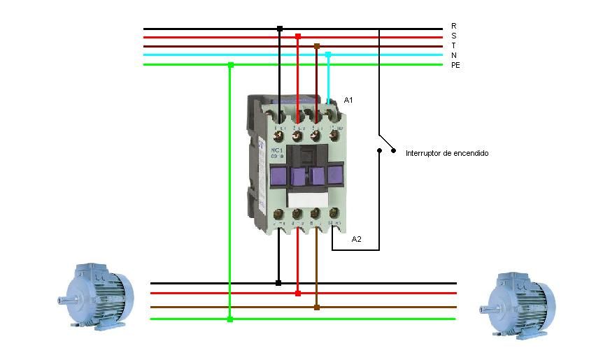
Magnetic contactor interlocking diagram. A detailed look at the design and application of reversing contactors. Contactors are used to provide this isolation. Disconnect circuit interrupter circuit breakers w thermal ol circuit breakers w magnetic ol limit switches foot switches pressure vacuum switches liquid level switches temperature actuated switches. Magnetic contactor https bit ly 3eucp11 bisitahin ang ating fb page https goo gl y8ys68 kung may mga katanungan kayo ay comment lang kayo sa baba at sasagutin ko hangat kaya ng aking nalalaman.
These voltages must be electrically isolated from the standard 120 volts ac. Contactors use 120 volt standard power to energize a magnetic coil which causes a set of internal contacts to close and provide higher power to the equipment. Use these tips to learn how to wire a contactor. When we push the on 1 button to energies the m1 contactor or starts m1 motor then circuit complete through fuse overload relay s trip link off push 1 and on push 1.
The diagram symbols in table 1 are used by square d and where applicable conform to nema national electrical manufacturers a ssociation standards. There is a wiring diagram and adjacent to it a line diagram line diagrams are included because their use is becoming more widespread and we believe it is advantageous to learn to use them. Wiring diagrams vs line diagrams most of the diagrams in this book are shown in two ways.

Sieno Jrs2 3ua Thermal Overload Relay Relay Thermal Audio Mixer

1951713082 This Topics Always Discussed Among Of Electrician

Switch Travel Limit Switch 15a Electrical Safety Key Interlock

Cjx2 1810 Ac Contactor 660v 32a 3 Phase 3 Pole No 36v 50 60hz Coil

Pin On Products

What Is Electrical Interlocking Power Control Diagrams With
Sieno Lc1 65 Thermo Magnetic Conbtactors Magnets Music Instruments

Voltage Regulation Of An Alternator Single Phase Transformer
Idea De Redo Graffiti En Electrical Instalacion Ventilador

Single Phase Split Ac Indoor Outdoor Wiring Diagram Ryb Electrical

Operation Structure In Tachometer Using Microcontroller

Star Delta Motor Change Direction Control Circuit

How Three Phase Electricity Works The Basics Explained Youtube

Types Of Motor Control Schematics Info Mechanics Pics Diagrama

